John Deere P540 Air Hoe Drill

Description
- Consistent seeding rates from row to row with RelativeFlow™ blockage monitoring
- Get in the field sooner with standard high-flotation package
- 3 Section - 40 Ft. - 12 In. Spacing
Models
Variety of fertilizer placement
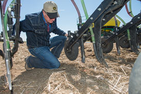
Whether using dry, liquid, or anhydrous ammonia, the John Deere P500 opener has the options that fit the application needs.
|
|
|
|
|
|
|
AA74478 Aqua anhydrous point |
AA69276 NH3 point |
AA74476 Liquid fertilizer point |
AA69277 Dry fertilizer point |
AA86117 Mud special point |
Description |
Austempered 10B38 boron steel point with hardfaced areas and induction fused carbide inserts to prevent wear. Carbide plates are 4-mm (0.16-in.) thick along the point edge and 6-mm (0.24-in.) thick on the tip. |
||||
Application |
Aqua anhydrous |
Anhydrous |
Liquid fertilizer |
Dry fertilizer** |
Dry fertilizer |
Option code |
1255 |
1250 |
1215/1220 |
--- |
1235 |
Tube diameter (OD) |
9.5 mm (3/8 in.) |
12.7 mm (1/2 in.) |
6.35 mm (1/4 in.) |
--- |
--- |
Pin on |
X |
X |
X |
X |
X |
High top |
X |
X |
X |
X |
X |
Suitable for dry conditions |
X |
X |
X |
X |
X |
Suitable for muddy conditions |
X* |
X* |
X* |
--- |
X |
Dry fertilizer tube add-on |
AA69271 |
AA69271 |
AA69271 |
AA69266 |
--- |
Weight |
0.9 kg (2 lb) |
0.97 kg (2.14 lb) |
0.88 kg (1.95 lb) |
0.86 kg (1.9 lb) |
1.7 kg (3.78 lb) |
Other information |
This form of ammonia is produced by dissolving ammonia gas in water.
AA69272 hose guide is required if dry fertilizer tube is not installed. |
Anhydrous ammonia is compressed into a clear, colorless liquid.
AA69272 hose guide is required if dry fertilizer tube is not installed. |
AA69272 hose guide is required if dry fertilizer tube is not installed. |
--- |
Replaces AA69279.
Wear-resistant hardfaced welds increased by 75 percent.
Thickness increase from 4 to 8 mm (0.16 to 0.3 in.).
Extra 12.7-mm (1/2-in.) weld added close to heavy wear area. |
*If not using dry fertilizer tube add-on **Dry tube required |
|||||
 Anhydrous high top tip (left) versus aqua anhydrous tip (right)
This picture shows the difference between the anhydrous high top and aqua anhydrous tips pictured in the chart above. On the left, the anhydrous high top has a thicker tube wall (1.3-cm [0.5-in.] outer diameter) than the aqua anhydrous tip, though the inner diameter of both tips are equal. The NH3 knives may also be used in combination with the included dry-delivery tube for those wanting to apply NH3 and dry fertilizers simultaneously in the same fertilizer trench.
Additional information for code 1235: the mud-proof combination of dry-fertilizer tube and tip, code 1235, is available for those applying dry fertilizers only. This is recommended for running in sticky, heavy clay-type soils. However, it works well in all soil types to prevent mud from plugging the fertilizer tube opening. This opener is included as base equipment.
If seeding with dry fertilizer only, this option is highly recommended. The fertilizer exits the tube at a lower point, allowing growers desiring to place fertilizer at shallower depths more consistently.
The lower fertilizer exit point also allows the fertilizer to get to the bottom of the trench when more fertilizer and seed separation is desired, and for those light soils that tend to cave in the trench before the fertilizer is placed.
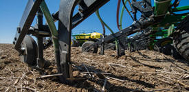 P500 fertilizer shanks engaged in the ground
| Fertilizer tubes | |
| 1.) AA69266 (1250) - Dry fertilizer |  |
| 2.) AA69271 (1220/50/55) - Dry fertilizer with NH3 or liquid |  |
| 3.) AA69272 (1215) - Liquid tube |  |
Confidence in rates from row to row with RelativeFlow™ Blockage sensing
With the RelativeFlow blockage sensing, operators can see the flow rate of both seed and fertilizer from inside the tractor cab. Sensors on all primary towers and secondary hoses monitor the relative product flow, giving you a better view of the flow rate of both seed and fertilizer from the cart to the opener from inside your tractor cab. This exclusive technology can help you identify any problems before potential blockage occurs.
RelativeFlow Blockage is available on the following models:
- P540 - 12.2-m (40-ft)
- P556 - 17.1-m (56-ft)
- P576 - 23.2-m (76-ft)
- N500C - all widths
- 1890 - 15.2-m (50-ft) and 18.3-m (60-ft)
- N530F - 9.1-m (30-ft)
- N540F - 12.2-m (40-ft)
- N543F - 13.1-m (43-ft)
- N560F - 18.3-m (60-ft)
RelativeFlow Blockage is compatible with hydraulic drive carts for model year 2014 and newer 1910, model year 2013 and newer 550 Carts, C650 and C850 Air Cart.
Below are the GreenStar™ 3 2630 Display screens for the blockage monitoring system. For complete details and information, see the owner’s manual.
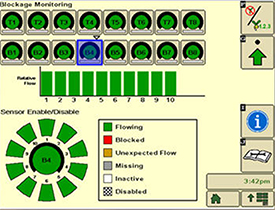 Blockage monitoring screen on GreenStar™ 3 2630
The RelativeFlow sensing chart shows the amount of flow through each sensor on the selected tower. Sensitivity for the blockage system can be adjusted if desired, as shown below.
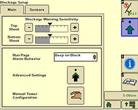 Blockage monitoring screen on GreenStar 3 2630
Blockage warning sensitivity allows the producer to set and change the sensitivity of the sensors to meet their preferences. Increasing the sensitivity means the system is more likely to show a false blockage, while less sensitivity means the system is more likely to miss a blockage.
Multiple run-page alarm behavior options are available for selection.
 Blockage monitoring screen on GreenStar 3 2630
Below are the Gen 4 display screens for the blockage monitoring system on the N500C.
For complete details and information reference, the owner’s manual.
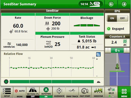 RelativeFlow Blockage configured run page
The SeedStar™ system run page displays the five major run settings. Clicking on any of the tiles will take an operator to that specific page (shown below).
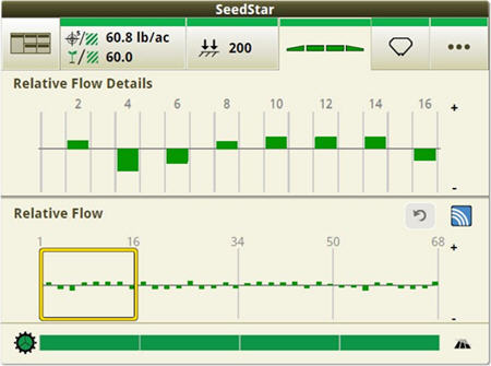 Operators can zoom into flow details by meter section when selecting blockage tiles
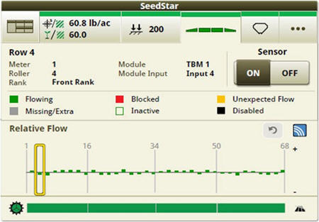 Operators can zoom into the row level to access row/sensor information and turn a sensor on/off independently
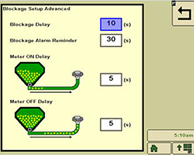
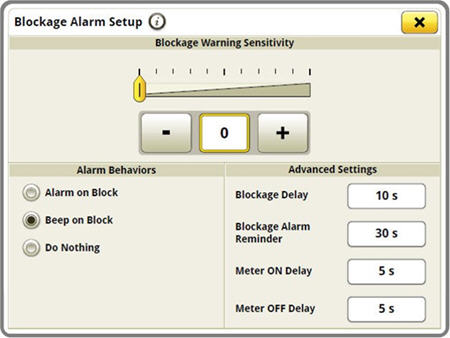 Blockage sensitivities and alarm delays are all set up on one easy-to-navigate screen
Blockage alarm delays can be set up by clicking on the advanced settings button from the blockage set-up screen.
- A blockage delay is how long a blockage should occur before an alarm is sounded.
- The blockage alarm reminder is how often the alarm should sound when a blockage occurs.
- The meter on delay is the time from when the meter is turned on until the blockage sensor should start monitoring for blockage.
- The meter off delay is the time from when the meter is turned off until the blockage sensor should start monitoring to verify no flow.
For more detailed information, see the owner’s manual.
Air tools with Relative Flow Blockage are not compatible with 1910 air carts with ground drive.
Row spacing options
Paired row vs. side banded
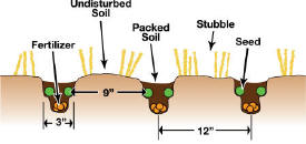 Paired row soil profile

The P500 has two cast seed boots available. Depending on a grower’s seed and fertilizer placement preference in different soils or different crops, the P500 can meet the user’s needs. The cast opener was designed with simplicity in mind. One tube is all that is necessary. Switching from single to paired row has never been easier; simply remove the two bolts holding the cast opener in place, remove the opener, and replace with the new opener.
Paired row
With shanks on 30.5-cm (12-in.) spacing, paired rows can be planted with 22.9-cm (9-in.) spacing. Seed is banded in two rows above and to the sides of the furrow. Total tillage in this zone is 7.6-cm (3-in.) wide with about 25 percent seedbed utilization (SBU).
Seed is laid on a 2-cm (0.75-in.) shelf while fertilizer is placed in a 2.5-cm (1-in.) band between and below the two seed rows.
With paired row placement, the crop is able to access the fertilizer when it needs it. The separation is enough to safely keep the seed from burning. The P500 provides a well-prepared seedbed for quick emergence and quicker canopy, which will help eliminate weeds. If the operator is looking to swath wider rows, support the heavy green crop.
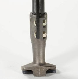 Paired row opener - rear shot
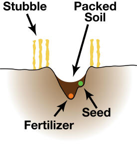 Single row/side banded soil profile

Side banded
If the seeding operation calls for side banding, the P500 is the needed tool. The side-banding seed tube places the seed on a firm bed of soil above and to the side of fertilizer as required. There are 30.5-cm (12-in.) rows across the machine with positive separation between seed and fertilizer up to 11.4 cm (4.5 in.). As the seed germinates and begins to emerge, its roots will be 7.6-cm to 10.2-cm (3-in. to 4-in.) deep and into the nutrient zone.
John Deere recognizes not all seeding conditions are identical and, with the P500, offers solutions to meet seed and fertilizer placement needs.
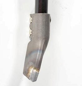 Single row/side banded
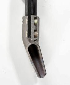 Single row/side banded - rear shot
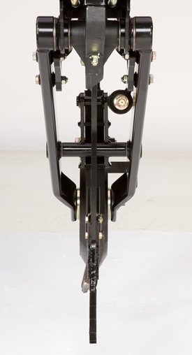 Single row seed boot in-line
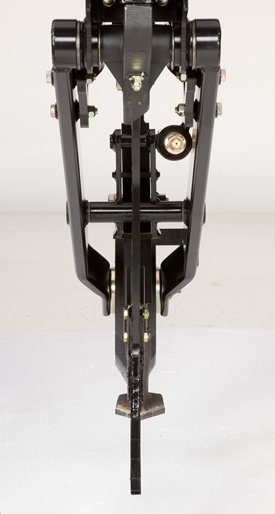 Paired row seed boot in-line
Features
- Working Width: 40 ft.
- Opener: Air Hoe Drill
- Row Spacing: 9-in. (23-cm) paired row 11.8-in. (30-cm) side band
- Transport Width: 19 ft., 22.6 ft
- Fertilizer Placement: In Furrow
Copy Set
Variety of fertilizer placement

Whether using dry, liquid, or anhydrous ammonia, the John Deere P500 opener has the options that fit the application needs.
|
|
|
|
|
|
|
AA74478 Aqua anhydrous point |
AA69276 NH3 point |
AA74476 Liquid fertilizer point |
AA69277 Dry fertilizer point |
AA86117 Mud special point |
Description |
Austempered 10B38 boron steel point with hardfaced areas and induction fused carbide inserts to prevent wear. Carbide plates are 4-mm (0.16-in.) thick along the point edge and 6-mm (0.24-in.) thick on the tip. |
||||
Application |
Aqua anhydrous |
Anhydrous |
Liquid fertilizer |
Dry fertilizer** |
Dry fertilizer |
Option code |
1255 |
1250 |
1215/1220 |
--- |
1235 |
Tube diameter (OD) |
9.5 mm (3/8 in.) |
12.7 mm (1/2 in.) |
6.35 mm (1/4 in.) |
--- |
--- |
Pin on |
X |
X |
X |
X |
X |
High top |
X |
X |
X |
X |
X |
Suitable for dry conditions |
X |
X |
X |
X |
X |
Suitable for muddy conditions |
X* |
X* |
X* |
--- |
X |
Dry fertilizer tube add-on |
AA69271 |
AA69271 |
AA69271 |
AA69266 |
--- |
Weight |
0.9 kg (2 lb) |
0.97 kg (2.14 lb) |
0.88 kg (1.95 lb) |
0.86 kg (1.9 lb) |
1.7 kg (3.78 lb) |
Other information |
This form of ammonia is produced by dissolving ammonia gas in water.
AA69272 hose guide is required if dry fertilizer tube is not installed. |
Anhydrous ammonia is compressed into a clear, colorless liquid.
AA69272 hose guide is required if dry fertilizer tube is not installed. |
AA69272 hose guide is required if dry fertilizer tube is not installed. |
--- |
Replaces AA69279.
Wear-resistant hardfaced welds increased by 75 percent.
Thickness increase from 4 to 8 mm (0.16 to 0.3 in.).
Extra 12.7-mm (1/2-in.) weld added close to heavy wear area. |
*If not using dry fertilizer tube add-on **Dry tube required |
|||||
 Anhydrous high top tip (left) versus aqua anhydrous tip (right)
This picture shows the difference between the anhydrous high top and aqua anhydrous tips pictured in the chart above. On the left, the anhydrous high top has a thicker tube wall (1.3-cm [0.5-in.] outer diameter) than the aqua anhydrous tip, though the inner diameter of both tips are equal. The NH3 knives may also be used in combination with the included dry-delivery tube for those wanting to apply NH3 and dry fertilizers simultaneously in the same fertilizer trench.
Additional information for code 1235: the mud-proof combination of dry-fertilizer tube and tip, code 1235, is available for those applying dry fertilizers only. This is recommended for running in sticky, heavy clay-type soils. However, it works well in all soil types to prevent mud from plugging the fertilizer tube opening. This opener is included as base equipment.
If seeding with dry fertilizer only, this option is highly recommended. The fertilizer exits the tube at a lower point, allowing growers desiring to place fertilizer at shallower depths more consistently.
The lower fertilizer exit point also allows the fertilizer to get to the bottom of the trench when more fertilizer and seed separation is desired, and for those light soils that tend to cave in the trench before the fertilizer is placed.
 P500 fertilizer shanks engaged in the ground
| Fertilizer tubes | |
| 1.) AA69266 (1250) - Dry fertilizer |  |
| 2.) AA69271 (1220/50/55) - Dry fertilizer with NH3 or liquid |  |
| 3.) AA69272 (1215) - Liquid tube |  |
Confidence in rates from row to row with RelativeFlow™ Blockage sensing
With the RelativeFlow blockage sensing, operators can see the flow rate of both seed and fertilizer from inside the tractor cab. Sensors on all primary towers and secondary hoses monitor the relative product flow, giving you a better view of the flow rate of both seed and fertilizer from the cart to the opener from inside your tractor cab. This exclusive technology can help you identify any problems before potential blockage occurs.
RelativeFlow Blockage is available on the following models:
- P540 - 12.2-m (40-ft)
- P556 - 17.1-m (56-ft)
- P576 - 23.2-m (76-ft)
- N500C - all widths
- 1890 - 15.2-m (50-ft) and 18.3-m (60-ft)
- N530F - 9.1-m (30-ft)
- N540F - 12.2-m (40-ft)
- N543F - 13.1-m (43-ft)
- N560F - 18.3-m (60-ft)
RelativeFlow Blockage is compatible with hydraulic drive carts for model year 2014 and newer 1910, model year 2013 and newer 550 Carts, C650 and C850 Air Cart.
Below are the GreenStar™ 3 2630 Display screens for the blockage monitoring system. For complete details and information, see the owner’s manual.
 Blockage monitoring screen on GreenStar™ 3 2630
The RelativeFlow sensing chart shows the amount of flow through each sensor on the selected tower. Sensitivity for the blockage system can be adjusted if desired, as shown below.
 Blockage monitoring screen on GreenStar 3 2630
Blockage warning sensitivity allows the producer to set and change the sensitivity of the sensors to meet their preferences. Increasing the sensitivity means the system is more likely to show a false blockage, while less sensitivity means the system is more likely to miss a blockage.
Multiple run-page alarm behavior options are available for selection.
 Blockage monitoring screen on GreenStar 3 2630
Below are the Gen 4 display screens for the blockage monitoring system on the N500C.
For complete details and information reference, the owner’s manual.
 RelativeFlow Blockage configured run page
The SeedStar™ system run page displays the five major run settings. Clicking on any of the tiles will take an operator to that specific page (shown below).
 Operators can zoom into flow details by meter section when selecting blockage tiles
 Operators can zoom into the row level to access row/sensor information and turn a sensor on/off independently
 Blockage sensitivities and alarm delays are all set up on one easy-to-navigate screen
Blockage alarm delays can be set up by clicking on the advanced settings button from the blockage set-up screen.
- A blockage delay is how long a blockage should occur before an alarm is sounded.
- The blockage alarm reminder is how often the alarm should sound when a blockage occurs.
- The meter on delay is the time from when the meter is turned on until the blockage sensor should start monitoring for blockage.
- The meter off delay is the time from when the meter is turned off until the blockage sensor should start monitoring to verify no flow.
For more detailed information, see the owner’s manual.
Air tools with Relative Flow Blockage are not compatible with 1910 air carts with ground drive.
Row spacing options
Paired row vs. side banded
 Paired row soil profile

The P500 has two cast seed boots available. Depending on a grower’s seed and fertilizer placement preference in different soils or different crops, the P500 can meet the user’s needs. The cast opener was designed with simplicity in mind. One tube is all that is necessary. Switching from single to paired row has never been easier; simply remove the two bolts holding the cast opener in place, remove the opener, and replace with the new opener.
Paired row
With shanks on 30.5-cm (12-in.) spacing, paired rows can be planted with 22.9-cm (9-in.) spacing. Seed is banded in two rows above and to the sides of the furrow. Total tillage in this zone is 7.6-cm (3-in.) wide with about 25 percent seedbed utilization (SBU).
Seed is laid on a 2-cm (0.75-in.) shelf while fertilizer is placed in a 2.5-cm (1-in.) band between and below the two seed rows.
With paired row placement, the crop is able to access the fertilizer when it needs it. The separation is enough to safely keep the seed from burning. The P500 provides a well-prepared seedbed for quick emergence and quicker canopy, which will help eliminate weeds. If the operator is looking to swath wider rows, support the heavy green crop.
 Paired row opener - rear shot
 Single row/side banded soil profile

Side banded
If the seeding operation calls for side banding, the P500 is the needed tool. The side-banding seed tube places the seed on a firm bed of soil above and to the side of fertilizer as required. There are 30.5-cm (12-in.) rows across the machine with positive separation between seed and fertilizer up to 11.4 cm (4.5 in.). As the seed germinates and begins to emerge, its roots will be 7.6-cm to 10.2-cm (3-in. to 4-in.) deep and into the nutrient zone.
John Deere recognizes not all seeding conditions are identical and, with the P500, offers solutions to meet seed and fertilizer placement needs.
 Single row/side banded
 Single row/side banded - rear shot
 Single row seed boot in-line
 Paired row seed boot in-line


